Intermatic Sprinkler Timer Wiring Diagram - A wiring diagram is a streamlined traditional photographic depiction of an electrical circuit.. A pool timer controls the pool pump's run time. The pump turns on and off manually just fine. Assortment of intermatic timer t104 wiring diagram. Intermatic timer t104 wiring diagram laptrinhx news. It's easy to install or replace an irrigation sprinkler controller.
The pump turns on and off manually just fine. Compare the old electrical wiring diagram on the cover door with the wiring diagram provided with your new timer. Variety of intermatic r8806p101c wiring diagram. Irrigation timer diagram design green building neutral floor plans rain wire. Swimming pool timer wiring diagram gallery.
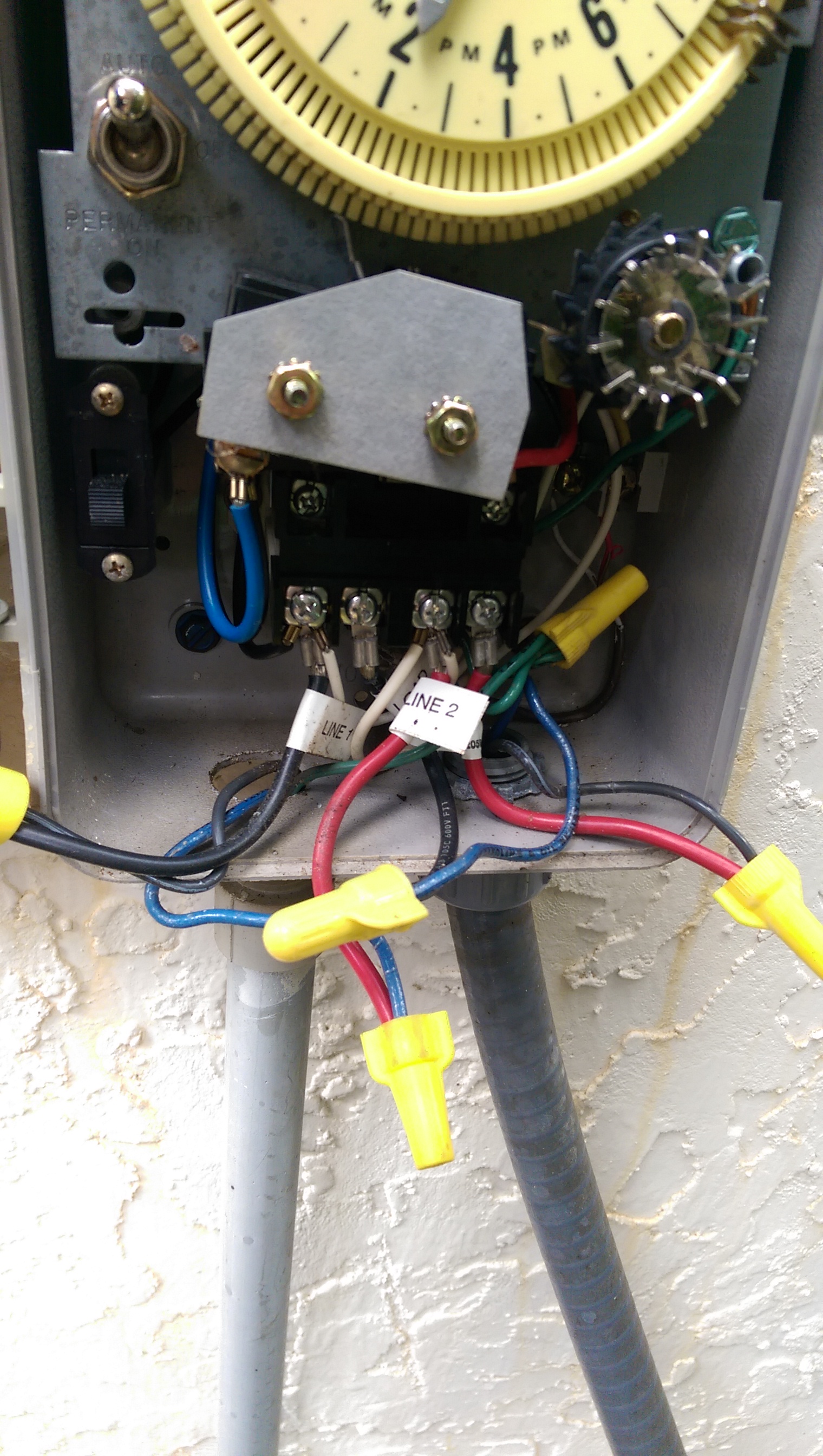
hmm might have jumped the gun | OpenSprinkler from opensprinkler.com Want to replace intermatic mechanical timer with electronic help diy home improvement forum. A wiring diagram is a streamlined traditional photographic depiction of an electrical circuit. The timer should snap in place with the spring loaded clip or bracket provided with your new timer. Intermatic t101 wiring diagram view 15 best intermatic t101 timer wiring diagram images. It shows the components of the circuit as streamlined shapes, and also the power as well as signal links in between the gadgets. Pull the sprinkler wires out of the timer. All intermatic timers can be shipped to you at home. Assortment of intermatic timer t104 wiring diagram.
A wiring diagram is a simplified traditional photographic depiction of an electric circuit.
Intermatic incorporated manufactures timer switches designed for indoor and outdoor use. Related posts of intermatic sprinkler timer wiring diagram two stage thermostat wiring diagram. The motor is working i can see it turning through the peep hole. 4.6 out of 5 stars 41. Assortment of intermatic t103 wiring diagram. Intermatic timer t104 wiring diagram laptrinhx news. Wiring instructions for an intermatic timer. Where the black hot wire goes. It reveals the components of the circuit as simplified shapes, as well as the power and signal links between the tools. The timer should snap in place with the spring loaded clip or bracket provided with your new timer. Intermatic is dedicated to providing energy management solutions for commercial residential and industrial markets. Assortment of intermatic timer t104 wiring diagram. Pull the sprinkler wires out of the timer.
If your timer has tabs, press down on the tab with the end of your screwdriver to make it easier to remove the wire. Touch device users, explore by touch or with swipe gestures. It reveals the components of the circuit as streamlined forms, and also the power and also signal links between the gadgets. A wiring diagram is a streamlined traditional photographic depiction of an electrical circuit. Assortment of intermatic timer t104 wiring diagram.
I have a new sprinkler timer; Intermatic Model ... from ww2.justanswer.com Riesenauswahl an produkten für zuhause. We show where to connect the neutral wire. Assortment of intermatic t103 wiring diagram. Intermatic mechanical timer replace sprinklers bcf7e orbit pump start relay wiring diagram review orbit bhyve smart wi fi sprinkler timer & controller mg 4279] pump start relay wiring diagram also pump start d3e1227 orbit wire diagram setting up rachio intermatic analog irrigation water timer orbit b hyve 6 station wifi irrigation controller & pump start relay free rain sensor users manual sp. If your timer has tabs, press down on the tab with the end of your screwdriver to make it easier to remove the wire. Compare the old electrical wiring diagram on the cover door with the wiring diagram provided with your new timer. Intermatic sprinkler timer wiring diagram sn 2694 photocell wiring diagram on intermatic time clock. 4.6 out of 5 stars 41.
When i connect it to the white neutral bar in the fuse box it trips the gfi same if i connect it to the ground bar.
These irrigation timers are designed to permit one to 44 on operations every 24 hours and provide watering increments down to 12 minutes or up to 20 hours and 45 minutes to ensure proper watering increments. If you need to buy a new one, find it on amazon:usa: Intermatic incorporated manufactures timer switches designed for indoor and outdoor use. It's easy to install or replace an irrigation sprinkler controller. Assortment of intermatic t103 wiring diagram. A wiring diagram is a streamlined traditional photographic depiction of an electrical circuit. Many pool pump motors and water heaters use intermatic timers to regulate their run times. Many pool pump motors and water heaters use intermatic timers to regulate their run times. The time switch shall be designed for water metering in increments of 12 minutes to a maximum of 20 hours and 45 minutes for precise water control. Irrigation timer diagram design green building neutral floor plans rain wire. It reveals the components of the circuit as streamlined forms, and also the power and also signal links between the gadgets. Rpc | sprinkler/irrigation time switch with day skipper these irrigation timers are designed to permit one to 44 on operations every 24 hours. Intermatic incorporated manufactures pool timers for residential use.
The timer should snap in place with the spring loaded clip or bracket provided with your new timer. Many pool pump motors and water heaters use intermatic timers to regulate their run times. A 8 pin timer are used. The motor is working i can see it turning through the peep hole. What are some of the most reviewed products in intermatic timers?
Intermatic Sprinkler Timer Wiring Diagram from schematron.org It shows the components of the circuit as streamlined shapes, and also the power as well as signal links in between the gadgets. Intermatic t86a transformer for sprinkler timer or install 20 amp line fuse between incoming hot wire and timer, and this will allow timer to control any. Notate the differences in the wiring if there are any and consider them before you begin to rewire the new. Intermatic timer t104 wiring diagram laptrinhx news. A pool timer controls the pool pump's run time. Intermatic mechanical timer replace sprinklers bcf7e orbit pump start relay wiring diagram review orbit bhyve smart wi fi sprinkler timer & controller mg 4279] pump start relay wiring diagram also pump start d3e1227 orbit wire diagram setting up rachio intermatic analog irrigation water timer orbit b hyve 6 station wifi irrigation controller & pump start relay free rain sensor users manual sp. Compare the old electrical wiring diagram on the cover door with the wiring diagram provided with your new timer. If your timer has tabs, press down on the tab with the end of your screwdriver to make it easier to remove the wire.
A wiring diagram is a streamlined conventional pictorial depiction of an electric circuit.
I will also post this in the electrical forum, but since it has to do with irrigation, i try here as well. Pool light transformer wiring diagram fresh intermatic pool timer. Many pool pump motors and water heaters use intermatic timers to regulate their run times. Intermatic pool timer wiring diagram download. Intermatic t101 wiring diagram view 15 best intermatic t101 timer wiring diagram images. Irrigation timer diagram design green building neutral floor plans rain wire. If your unit has the wire attached with screws, use a screwdriver to loosen the connection and pull the wire out. Touch device users, explore by touch or with swipe gestures. Need the wiring for the need the wiring for the intermatic rpc irrigation timer 14 day. When i connect it to the white neutral bar in the fuse box it trips the gfi same if i connect it to the ground bar. If your timer has tabs, press down on the tab with the end of your screwdriver to make it easier to remove the wire. A wiring diagram is a streamlined conventional pictorial depiction of an electric circuit. Assortment of intermatic timer t104 wiring diagram.
Intermatic sprinkler timer wiring diagram sn 2694 photocell wiring diagram on intermatic time clock intermatic sprinkler timer wiring. Intermatic timer t104 wiring diagram laptrinhx news.


0 Komentar